One of the most fun parts of doing biology research, in my opinion, is designing equipment to take the kinds of measurements and gather the kind of data that you need. I designed a couple pieces of lab and field equipment in grad school and have continued using those pieces over the years.
As part of building a new research lab, specifically aimed at undergraduate research, on a shoestring budget, I’m trying to refine some of these homegrown pieces of equipment that were ok for me to use, but need to be more robust (i.e. less prone to user error) before undergrad researches can start using them.
Two such pieces of equipment are the two photography setups I have for photographing toe pads of preserved specimens in a lab setting and photographing live specimens in the field. Both of these photography rigs were built with the explicit purpose of imaging toe pads with as little distortion as possible. A big part of this goal is making sure the camera is pointed perfectly perpendicular to the toe pads. Previously I’ve eye-balled this or used bubble levels, knowing its a likely source of error in my data.
In order to reduce this potential error, I reached out to the Mississippi State University Center for Advanced Vehicular Systems machine shop over in Starkville and asked if they could CNC some brackets for me. Working with Mike Newman, I designed the brackets in the FreeCAD software. I’ve used Google SketchUp previously to build parts for 3D printing, but I learned that the files for CNC machining (.iges) are different than what works for 3D printing (.stl) and that Google SketchUp can’t output .iges files..
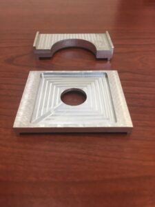
I am excited to share that these aluminum brackets turned out great!
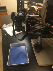
 The top bracket was build to hold a camera quick release mount pointing straight downwards to image preserved specimens in a tray.
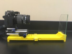
 The second bracket was built to hold the same quick release perpendicular to a vertical piece of glass for imaging the toes of live lizards.